Headphone Driver Motor and Parameter Estimation


To start our ficticious headphone, we need to assume some basic parameters that will describe basic low frequency performance. I usually start this process by defining the motor, choosing realistic wire size, coil dimensions, magnet grade etc..
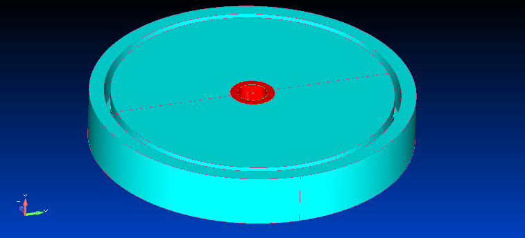
I created a motor system including bass port and developed this into a 2D axisymmetric finite element model to predict the effective flux density in the motor gap which, when combined with the voice coil parameters would determine the Lorentz force. This effectively definies the motor strength and electromagnetic damping. The magnet is assumed to be a Neodymium Iron Boron (NdFeB) rare earth type in a shellpot topology. The top plate, magnet and backplate all have a hole through to allow for the plastic bass port.
 |
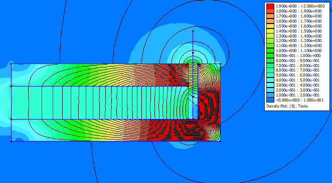 |
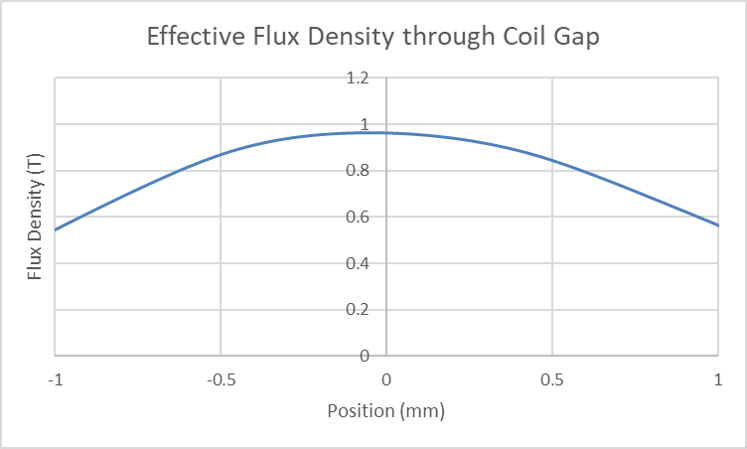
The output from the axisymmetric finite element model shows that the steel in the motor is rather saturated. The effective flux density sampled in the motor gap is shown in the chart below.
Flux Density (averaged over coil winding width)
Combining the predicted motor results with additional physical parameters estimated from the initial CAD model allows a more complete definition of the driver to be made. Defining parameters enables some basic low frequency behaviour to be predicted.
Defined Parameters
| Wire Size (mm) | 0.05 | |
| No.Layers | 2 | |
| Former ID (mm) | 19.3 | |
| Winding Width (mm) | 2 | |
| Conductor | Cu | |
| Force Factor (N/A) | 3.1 | |
| Re (Ohm) | 33.9 | |
| Sd (cm^2) | 7.4 | |
| Cms (m/N) | 0.00667 | |
| Mms (g) | 0.236 | |
| Fs (Hz) | 127 | |
| Qes | 0.68 | |
| Qms | 9 | |
| Qts | 0.68 |
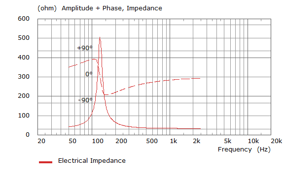
The basic performance of the driver for an excitation voltage of 150mV measured on axis at 100mm. This lumped model assumes that the driver is mounted in an infinite baffle radiating into a free field of 2Pi steradians.
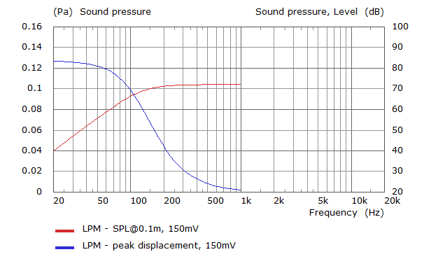
Note that the electrical impedance is only a low frequency prediction assuming negligable "lossy inductor" effects