Vacuum Chamber Measurements


Vacuum chambers are useful when investigating transducers that may be heavily influenced by acoustic airloads. In the case of the headphone driver, it should be possible to isolate some damping mechanisms that are attibutable to the viscous effects of air which may be forced to oscilate in narrow channels or through porous/ fibrous media. If the air is removed from the system, it follows that the associated damping is eliminated.
The effect of frame vent damping was investigated as it was assumed that this damping could be removed using a vacuum chamber capable of producing a pressure difference of 1Bar.
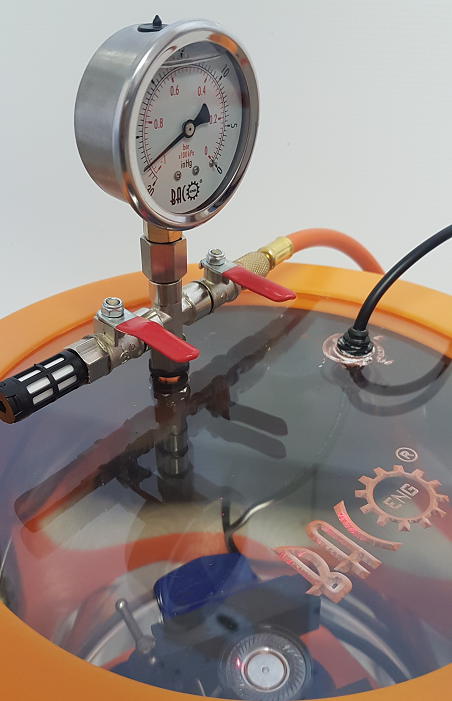
Photo of vacuum chamber with clear lid, facilitating measurements using a laser Doppler velocimeter.
Velocity measurements below show the difference in diaphragm mobility (measured at the top of the voice coil) under normal air-loaded conditions, and then when the air is removed from the chamber.
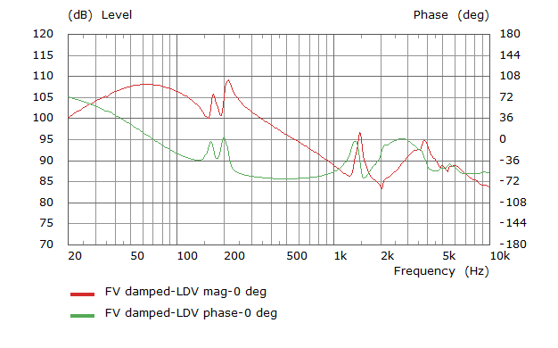
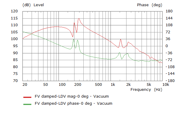
The removal of air from the system increases the diaphragm mobility over a large portion of the frequency range above ~60Hz and appears to reduce damping on the rocking mode at ~200Hz, which is also shifted slightly higher in frequency. Acoustical resonance effects, that affect the coupled diaphragm between ~1.4kHz and 6kHz are also eliminated.
Effect on the Electrical Impedance
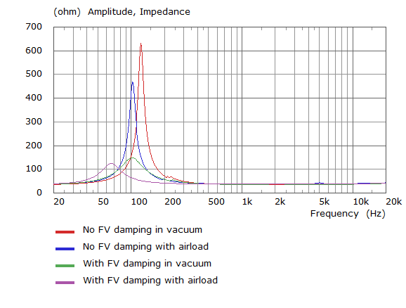
Damping in vents has major effect on electrical impedance resulting in a change in Zmax from 470 to 120 Ohms. To confirm that the frame damping is the cause of such a variation in ZMax, the driver was put into a vacuum chamber and electrical impedance measurements repeated. The idea was that if the airload could be removed, both the drivers should measure equivalently and any visco-thermal damping effects eliminated.
The vacuum chamber does not completely remove the air as a perfect vacuum is never achieved, however the difference achieved from atmospheric pressure was down to -0.98 Bar, which was initially felt to be a substantial change. The coil appears to be very sensitive to the presence of air and the damping effect of acoustical absorption.
The measured impedances show that when the airload is diminished, the resonance shifts higher and Zmax increases. The anticipated outcome was that in the vacuum, the impedance with the frame vent damping would overlie the impedance without the frame vent damping (green vs red in the chart below), but this clearly was not the case.
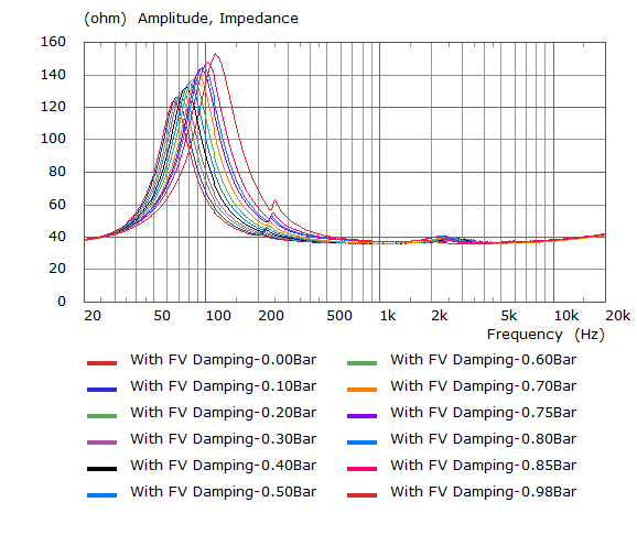
The difference in resonance frequencies and magnitude of Zmax between the drivers in the vacuum suggests that some residual airload exists. This was tested by pumping as much air as was safely possible from the chamber and making electrical impedance measurements as air was re-introduced. The initial value at -0.98 Bar has a resonance close to that of the driver wihout frame damping, though ZMax is much lower. The successive measurements as air was admitted produced a family of data (below) which might extrapolate to suggest a vacuum that would produce an equivalance between the drivers. It is believed that the change in resonance would be small, but the change in ZMax large at increased vacuum beyond the capability of the equipment.
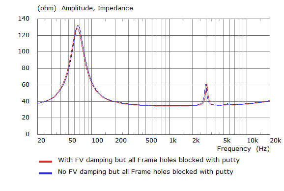
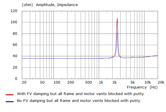
As a sanity check, blocking the frame vent holes on both drivers as an alternative route to establish equivalence between the drivers confirms that the only major difference between the drivers is the damping in the frame vents. This is shown below where acoustic damping elements are blocked using putty.